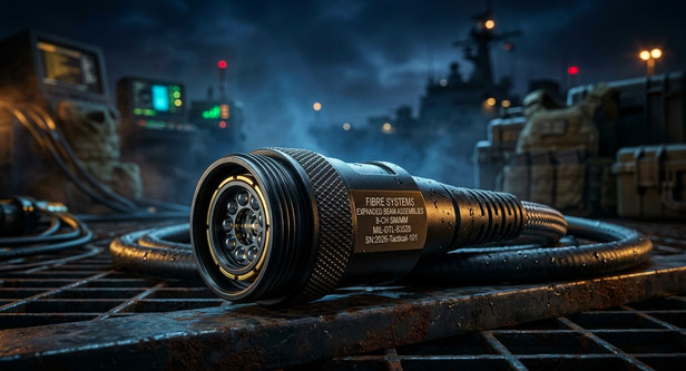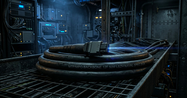
MTP/MPO Connectivity Platforms provide the critical high-density infrastructure required for modern data centers, naval vessels, and high-performance industrial networks. As bandwidth demands escalate and network architects squeeze maximum port capacity into shrinking rack spaces, the traditional approach of managing thousands of individual fiber connectors becomes a logistical and operational nightmare. Fibre Systems designs and manufactures premium multi-fiber connectivity solutions that consolidate cable infrastructure, dramatically reduce installation times, and guarantee optimal optical performance in critical environments.
The exponential growth in data traffic, driven by cloud computing, high-definition video streams, and automated systems, necessitates a shift from serial 10G links to parallel 40G, 100G, and even 400G transmission. Attempting to achieve this migration using standard LC or SC connectors leads to unmanageable cable spaghetti inside patch panels, creating severe cooling bottlenecks and increasing the risk of accidental cable damage during maintenance. A single mismanaged cable bundle can choke airflow, causing active equipment to overheat and leading to devastating network downtime.
Furthermore, high-density environments amplify the consequences of sub-standard connector performance. When deploying parallel optics, the aggregate insertion loss across a complex multi-fiber link must be meticulously controlled. Poorly engineered multi-fiber connectors often suffer from uneven ferrule pressure or precise alignment failures, resulting in expensive signal attenuation nightmares that trigger high bit error rates and cripple network throughput. Implementing a robust MTP/MPO framework is no longer optional; it is the fundamental prerequisite for reliable, scalable high-speed data transmission.
What Is an MTP/MPO Connectivity Platform Component?
An MTP/MPO Connectivity Platform component is a comprehensive system designed to consolidate numerous individual fiber optic strands into a single, high-density interface. MPO stands for Multi-Fiber Push-On, the international standard (IEC 61754-7) defining the interface dimensions and intermateability of multi-fiber connectors. MTP is a brand name for a specific, enhanced MPO connector manufactured by US Conec, which includes significant mechanical and optical performance improvements over generic MPO designs.
The defining feature of this platform is the rectangular ferrule capable of housing 12, 24, 48, or even 72 fiber strands simultaneously in a single connector housing. This architecture enables simultaneous termination of all fibers within the ferrule in one action, radically compressing the physical footprint required for high-port-count installations. MTP/MPO connectors utilize dynamic spring-loaded ferrules and precision guide pins to maintain the exact axial and lateral alignment required for low-loss transmission across every fiber strand.
Deploying MTP/MPO Connectivity Platforms provides a modular, plug-and-play approach to high-density fiber patching. By utilizing standardized components, such as multi-fiber trunks, pre-terminated cassettes, and high-density panels, network engineers establish scalable infrastructure that accommodates future bandwidth expansion without requiring costly and labor-intensive field splicing or individual fiber routing.
Utilizing a premium MTP/MPO system ensures that high-speed parallel optical transceivers operate at peak efficiency. When signal budgets are extremely tight, the sub-micron ferrule alignment and controlled end-face geometry of high-performance connectors minimize both insertion loss and return loss, maximizing overall link stability.
Common Challenges in High-Density Fiber Environments
Achieving maximum port density while maintaining robust network reliability introduces unique physical and optical challenges that overwhelm traditional single-fiber connectivity methods.
- Severe Patch Panel Congestion (Cable Chaos): Managing thousands of duplex LC patch cords within a single rack generates unmanageable clutter, blocking access to ports and making moves, adds, and changes (MACs) a significant operational risk.
- Expensive Signal Attenuation (Insertion Loss) Issues: Generic multi-fiber connectors often struggle to maintain consistent ferrule pressure across 12 or 24 strands. Slight misalignment causes expensive signal attenuation nightmares on outer fibers, impacting total link performance.
- Complex Polarity and Fiber Mapping Errors: When deploying multi-fiber trunks, ensuring that the transmit fiber at one end connects to the correct receive fiber at the remote end becomes extremely complex. Inconsistent polarity methods lead to link failures and costly troubleshooting delays.
- Airflow Obstruction and Equipment Overheating: Massive bundles of patch cords draped across the front of high-density chassis block critical cold air intake paths, significantly increasing the operating temperature of expensive active networking hardware.
- Vulnerability to Guide Pin and Ferrule Damage: Multi-fiber connectors rely on precision guide pins or holes for alignment. Improper mating force or contamination can easily damage these critical interfaces, resulting in permanent optical failure.
Integrating a robust MTP/MPO Connectivity Platforms solution directly resolves these density and performance bottlenecks. By pre-engineering fiber paths and consolidating links into multi-fiber connectors, network architects eliminate patching chaos while guaranteeing the low-loss performance required for high-speed transmission.
Technical Performance Standards for MTP/MPO Connectivity Platform Hardware
Understanding the optical and mechanical specifications of MTP/MPO components is essential for selecting hardware that supports multi-gigabit parallel transmission without introducing excessive insertion loss.
- Fiber Count Flexibility: Offers configurations supporting 8, 12, 16, 24, 32, 48, or 72 fiber strands within a single ferrule interface.
- Optical Loss (Insertion Loss) Rating: High-performance MTP/MPO components are classified as Low Loss or Ultra-Low Loss, with typical random mate insertion loss of less than 0.35 dB, ensuring link budgets remain intact for 100G+ data rates.
- High Return Loss (Reflectance): Utilizes APC (Angled Physical Contact) polishes for singlemode fibers, providing return loss greater than 60 dB to prevent destabilizing back-reflections into high-power laser transmitters.
- Precision Ferrule Alignment: MTP connectors incorporate high-precision composite ferrules and controlled guide pin tolerances to ensure exact fiber-to-fiber alignment across every mating cycle.
- Gender and Polarity Standards: Adheres to established standards (TIA-568-C.3) for defining connector gender (Pinned/Unpinned) and polarity methods (Type A, Type B, Type C) to guarantee correct end-to-end fiber mapping.
- Environmental Resistance: Standard housings are designed for controlled data center environments; ruggedized variations are available to withstand the vibration and thermal stress found on naval vessels and industrial sites.
Comparison: US Conec MTP vs. Generic MPO Multi-Fiber Connectors
The terms MTP and MPO are often used interchangeably, but significant engineering differences affect optical performance, physical durability, and ease of use in the field. This detailed comparison pastes cleanly into Word or engineering documentation.
| Technical Evaluation Criteria | US Conec MTP Connector | Generic MPO Connector |
| Ferrule Construction | High-precision thermoplastic | Variable material quality |
| Alignment Mechanism | Enhanced elliptical guide pins | Standard round guide pins |
| Random Mate Insertion Loss | Typically ≤ 0.35 dB (Low Loss) | Often ≥ 0.60 dB |
| Insertion Loss over Cycles | Stable over 1,000 mating cycles | Degradation observed earlier |
| Guide Pin Retention Strength | High (Spring-loaded retention) | Lower retention force |
| Polarity / Gender Changes | Rapid field-changeable options | Fixed configuration (Factory build) |
| Overall Mechanical Durability | Exceptional (Engineered for reuse) | Standard durability limits |
Deploying US Conec MTP components within MTP/MPO Connectivity Platforms eliminates the uncertainty associated with generic MPO hardware. The enhanced elliptical guide pins are less prone to scratching the delicate vertical surfaces of the ferrule hole, preserving sub-micron alignment tolerances after hundreds of connections.
Choosing a premium platform ensures consistent contact pressure across all fibers. When budget signal analysis determines margins are critically tight, using Ultra-Low Loss MTP connectors often provides the crucial fractional decibel savings required to pass link certification and avoid expensive troubleshooting delays.
Addressing High-Density Cabling Complexity and Airflow Challenges
MTP/MPO Connectivity Platforms redefine how fiber infrastructure is structured inside crowded equipment racks. By replacing dozen duplex LC patch cords with a single multi-fiber trunk, these systems provide an immediate and drastic reduction in cabling bulk.
A single 12-fiber MTP trunk cable occupies the same cross-sectional area as two duplex patch cords, yet delivers six times the signal capacity. This consolidation opens critical pathways within cable managers and overhead trays, restoring airflow access to active equipment chassis and preventing heat-related active component failure.
Implementing modular MTP/MPO Connectivity Platforms allows for a structured, two-tiered patching approach. High-fiber-count trunks establish the permanent horizontal or vertical cabling backbone, connecting main distribution frames (MDFs) to equipment distribution areas (EDAs). Pre-terminated cassettes then break out these trunk lines into standard LC duplex ports at the active equipment, keeping patching congestion contained within manageable, localized panels.
Furthermore, this modular approach simplifies Moves, Adds, and Changes. Rather than tracing thousands of individual patch cords, technicians only manage short patch links at the breakout panel, dramatically reducing operational risk and the potential for costly patching errors during high-pressure network reconfigurations.
Strategies for Managing Polarity in MTP/MPO Parallel Optics
Maintaining the correct optical polarity, ensuring that the transmitter at one end talks to the receiver at the remote end, is the most complex challenge when implementing MTP/MPO Connectivity Platforms. Without a structured polarity method, parallel optical links fail instantly.
The TIA-568 standard defines three different polarity methods to maintain correct fiber mapping across multi-fiber systems:
- Method A (Straight-Through): Connects Fiber 1 to Fiber 1 at both ends, utilizing Type A MTP adapters (Key-Up to Key-Down) and Method A patch cords. This method maintains simple mapping but complicates duplex patching requirements at the breakout.
- Method B (Flipped): Flips the fiber position at one end, connecting Fiber 1 to Fiber 12. This approach utilizes Type B MTP adapters (Key-Up to Key-Up) and simplifies LC duplex patching by maintaining a single patch cord type.
- Method C (Pairs): Flips adjacent fiber pairs inside the MTP trunk. Method C requires specialized adapters and patch cords, often adding unnecessary logistical complexity and increased insertion loss to the system design.
Selecting a standardized polarity strategy is critical. Most modern data center architectures utilize Method B for parallel optics due to its simplified patch cord management. The critical advantage of investing in advanced MTP/MPO Connectivity Platforms is that polarity is pre-engineered within the cassettes and trunks, ensuring consistent and guaranteed end-to-end connectivity right out of the box.
Using the wrong polarity configuration often results in zero light signal transmission and triggers expensive signal attenuation nightmares as engineers spend hours troubleshooting and re-mapping individual fiber connections in futile attempts to rectify the systemic issue.
MTP/MPO Implementation Guidelines for High-Speed Naval and Industrial Networks
While MTP/MPO Connectivity Platforms were originally optimized for clean data center environments, they are increasingly deployed across high-speed naval vessel networks, mining operations, and industrial manufacturing sites.
However, deploying delicate multi-fiber connectors in harsh environments requires robust protective measures to prevent catastrophic alignment failure caused by vibration, chemical ingress, or physical shock.
- Vibration and Thermal Management: High-performance composite MTP ferrules must maintain constant physical contact force during continuous machinery vibration or hull stress. Ruggedized connectors utilize robust metal shell housings and enhanced spring tensions to damp vibration and preserve optical stability.
- Contamination Control Protocols: The large rectangular ferrule of multi-fiber connectors is particularly susceptible to dust contamination. A single microscopic salt particle can obstruct multiple fiber cores simultaneously. Advanced dry cleaners specifically designed for MTP/MPO interfaces are mandatory for every connection cycle.
- Corrosion Resistance: Marine and mining environments are saturated with corrosive salt spray, fuel vapors, or dust particulates. Deploy MTP/MPO connections inside NEMA 4X or IP67 rated environmental enclosures, utilizing protective strain relief boots to prevent chemical attack on connector bodies.
- Compliance with ACMA Regulations: Adherence to the Australian Communications and Media Authority cabling standards is critical for all vessel installations. Certified MTP/MPO components must meet stringent low-smoke, zero-halogen (LSZH) requirements to prevent toxic gas emissions in enclosed shipboard compartments during fire events.
Adhering to AS/CA S008 standards ensures that MTP/MPO Connectivity Platforms deployed across Australian commercial ports or industrial processing plants satisfy necessary fire safety and toxic fume emission regulations, preventing hazardous conditions during high-temperature electrical faults inside sealed marine compartments. In high-density network environments, integrating certified MTP/MPO Connectivity Platforms streamlines cable routing while maintaining strict structural compliance under harsh operating conditions. Engineering teams frequently specify MTP/MPO Connectivity Platforms to eliminate patch panel chaos and protect core signal integrity across demanding industrial facilities. Furthermore, deploying ruggedized MTP/MPO Connectivity Platforms reduces installation footprint and minimizes risk during rapid infrastructure expansion. Ultimately, selecting high-performance MTP/MPO Connectivity Platforms provides a reliable, future-proof foundation for critical data backbones.
Step-by-Step Field Installation and Cleaning of MTP/MPO Connectors
Proper field installation techniques and meticulous cleaning procedures are paramount to the successful deployment of MTP/MPO Connectivity Platforms.
Step 1: Pre-Install Inspection of Enclosures and Contamination Check
Verify that all patch panels, bulkheads, and cassettes are mounted securely and that standard SC or LC ports on the breakout side are clean. Utilize a specialized multi-fiber inspection scope to check every MTP/MPO ferrule end-face (pinned and unpinned) for contamination immediately before mating.
Step 2: Perform Dry-Cleaning of MTP/MPO Connector Ferrules
If contamination is detected, perform dry-cleaning using a dedicated MTP/MPO clicker cleaner. Insert the cleaner tip into the adapter or directly onto the connector ferrule and activate the cleaning tape cycle. Never use standard LC or SC cleaning tools on multi-fiber interfaces.
Step 3: Verify Connector Gender and Key Polarity
Ensure that you are connecting a pinned connector (male) to an unpinned connector (female). Verify the keyway orientation (Key-Up/Key-Down) of the adapters matches the intended polarity method of your system (Type A or Type B) before attempting to mate connectors.
Step 4: Mate Connectors and Tactilely Verify Latching
Align the keyway latch of the MTP connector with the guide slot on the adapter housing. Push the connector body gently into the adapter until you feel and hear a distinct mechanical click, verifying the push-pull mechanism is fully engaged.
Step 5: Secure Proper Strain Relief and Manage Multi-Fiber Bundles
Secure MTP trunk cables to the internal cable management bar of the high-density panel or cassette, ensuring the cable bend radius remains well above the minimum specification (typically ten times the cable diameter) to prevent expensive signal attenuation nightmares caused by micro-bending.
Field Maintenance and Optical Testing Protocols for MTP/MPO Networks
Routine field maintenance and rigorous post-installation testing are critical for preventing latent network degradation and ensuring link performance meets 100G+ design standards.
- Semi-Annual Contamination Inspection: Conduct semi-annual inspections of active MTP/MPO patch panel ports, utilizing a digital fiber scope to capture high-resolution end-face images. Any sign of particulate accumulation requires immediate dry-cleaning.
- Comprehensive Multi-Fiber Insertion Loss Testing: Conduct comprehensive end-to-end insertion loss testing on every 12-fiber link using a specialized multi-fiber Optical Loss Test Set (OLTS). Measure total attenuation against the pre-calculated system budget to guarantee link performance.
- MTP/MPO Polarity Verification: Verify the polarity method (Method A or Method B) and fiber-to-fiber mapping using an MTP polarity tester. This rapid field test immediately identifies mapping errors and prevents incorrect patching configurations that cause signal failures.
- Vibration and Mechanical Retention Checks: Quarterly inspect ruggedized MTP connectors deployed in high-vibration engine rooms or machinery spaces, ensuring metal shells show no signs of corrosion and locking mechanisms retain their secure tactile engagement.
Dust contamination remains the leading cause of permanent optical link failure. Unprotected MTP/MPO ports accumulate fine airborne salt particles. When a technician inserts a multi-fiber trunk without cleaning, these particles smash against multiple ceramic ferrules under high spring tension, permanently pitting delicate glass end-faces across twelve fibers.
Maintaining an absolutely clean MTP/MPO connection environment extends hardware operational lifespan. Implementing strict contamination control protocols saves data center and vessel operators tens of thousands of dollars in emergency network restoration and equipment replacement costs.
Transitioning Legacy 10G Infrastructure to Parallel 40G and 100G Ethernet
Migrating critical network backbones from serial 10G to parallel 40G, 100G, and 400G Ethernet protocols is the primary driver for implementing high-performance MTP/MPO Connectivity Platforms.
A traditional 10G Ethernet link utilizes duplex transmission across two single fibers: one for transmit (Tx) and one for receive (Rx). Parallel optical transceivers, however, utilize multiple fiber strands simultaneously to achieve higher aggregate bandwidth. A 12-fiber MTP connector is required to support one 100G BASE-SR4 parallel link, which uses four fibers to transmit and four fibers to receive simultaneously, utilizing 8 of the 12 fibers within the ferrule.
Implementing a robust MTP/MPO trunk backbone provides a seamless and modular upgrade path. Legacy 10G links utilize MTP-to-LC cassettes to break out multi-fiber trunks into standard duplex ports. When upgrading to 100G, technicians simply replace the 10G cassette with an MTP adapter plate, enabling direct parallel optical transceiver patching over the existing MTP backbone without requiring a complete infrastructure retrofit.
This plug-and-play modularity minimizes active equipment downtime and operational risk during critical high-speed network upgrades. By investing in scalable MTP/MPO Connectivity Platforms, organizations future-proof their high-speed network investment, accommodating escalating bandwidth demands seamlessly across their multi-fiber infrastructure.
Deploying MTP/MPO Solutions for High-Performance Naval Computing and Sensor Systems
Modern naval frigates and commercial research vessels increasingly utilize high-performance computing clusters and massive sensor arrays that generate and process petabytes of data. Connecting these critical systems necessitates high-density, low-loss multi-fiber backbones capable of surviving the vibration and thermal shock found onboard the ship.
Deploying a high-performance MTP/MPO system enables naval architects to consolidate dense fiber sensor links into streamlined trunk cables, significantly reducing weight and spatial footprints inside tight shipboard cable trays. Every MTP connection point sourced from accredited manufacturers undergoes rigorous environmental stress testing to ensure performance meets naval-grade vibration and mechanical shock specifications.
Furthermore, integrating advanced MTP/MPO Connectivity Platforms into shipboard networks facilitates the rapid deployment of advanced sensor platforms and tactical computing nodes. Modular MTP breakout assemblies allow technicians to extend high-speed 40G or 100G links to remote sensor compartments with minimal downtime, ensuring maximum data availability during mission-critical operations.
Protecting these multi-fiber interfaces from particulate contamination inside harsh maritime engine rooms or radar compartments is paramount. Every deployment must utilize ruggedized environmental enclosures and strict contamination control protocols to preserve signal budgets and prevent expensive signal attenuation nightmares that compromise vessel operations.
Enhancing Data Center Manageability and Operational Efficiency
High-density data centers, particularly those supporting hyperscale or cloud operations, operate at the spatial and logistical limit. Managing thousands of individual fiber strands across multiple meet-me rooms, distribution frames, and equipment racks becomes a critical constraint on operational efficiency.
Integrating comprehensive MTP/MPO Connectivity Platforms provides immediate and dramatic improvements in data center spatial utilization and overall operational manageability. Consolidating links into multi-fiber trunk cables frees critical rack space, restoring airflow access to active equipment chassis and preventing costly active component overheating.
Furthermore, utilizing modular MTP/MPO breakout assemblies simplifies patch cord manageability. Technicians manage shorter, more contained LC duplex patch leads at the localized breakout panel, reducing operational risk and the potential for costly patching errors during moves, adds, and changes.
The pre-engineered nature of modular MTP/MPO platforms accelerates network deployment times significantly. Rather than tedious field splicing or individual fiber routing, technicians execute a simple plug-and-play installation of pre-terminated trunk cables and cassettes, ensuring high-speed fiber infrastructure is active and certified within hours rather than days.
Frequently Asked Questions
What is the primary difference between MTP and MPO connectors?
MPO (Multi-Fiber Push-On) is the generic international standard (IEC 61754-7) defining the Multi-Fiber Push-On connector interface. MTP is a registered trademark of US Conec and refers to a specific, enhanced MPO connector engineered with significant mechanical and optical improvements to guarantee superior optical performance and long-term durability over standard MPO connectors.
Can high-density MTP/MPO systems cause expensive signal attenuation nightmares?
Yes. If sub-standard connectors or improper cleaning protocols are used, uneven ferrule pressure or precise alignment failures can cause expensive signal attenuation nightmares, triggering high bit error rates and crippling 100G+ data throughput. Utilizing premium, low-loss MTP components and strict contamination control is essential to preventing link performance issues.
What is the maximum fiber count available in a single MTP/MPO ferrule?
While 12 and 24-fiber MTP connectors are the most common in data center and parallel optics applications, advanced MTP/MPO ferrule technologies support up to 72 fiber strands (three rows of 24 fibers) within a single connector interface for extreme high-density applications.
Is polarity management complex in high-density parallel optics?
Yes. Ensuring correct end-to-end fiber mapping (Transmitter to Receiver) in a multi-fiber system requires a structured polarity method (Method A or Method B) defined by standards. Incorrect polarity mapping instantly fails parallel optical links. Implementing comprehensive MTP/MPO Connectivity Platforms ensures that polarity mapping is pre-engineered within cassettes and trunks, guaranteeing consistent, plug-and-play connectivity.
Why is guide pin alignment critical in MTP/MPO connectors?
Guide pins in pinned (male) MTP connectors align the delicate fiber array within the ferrule with the corresponding guide holes in unpinned (female) connectors. Precise alignment tolerances are sub-micron. Guide pin damage or excessive wear will immediately result in ferrule misalignment, high optical insertion loss, and potential signal attenuation nightmares.
Strategic Summary
- MTP/MPO Connectivity Platforms consolidate twelve to seventy-two fiber strands within a single, high-density rectangular ferrule, radically compressing cabling bulk in crowded data center and vessel environments.
- Premium MTP components, featuring US Conec enhancements, provide elliptical guide pins and controlled spring pressure to guarantee optimal ferrule alignment, minimizing expensive signal attenuation nightmares across all fibers.
- Implementing comprehensive MTP/MPO systems eradicates patch panel chaos, restoring airflow access to active equipment chassis and mitigating the operational risks of overcrowded duplex LC patching.
- Pre-engineered polarity mapping within standardized MTP/MPO trunks, adapters, and cassettes ensures consistent plug-and-play parallel optics, eliminating the complexity of manual fiber mapping.
- Continuous optical testing and meticulous contamination control using multi-fiber specific dry cleaners are paramount for preventing guide pin wear and preserving signal budget stability in 100G+ parallel networks.
Eradicate Patch Panel Chaos with Fibre Systems MTP/MPO Platforms Now
High-speed data centers and critical industrial networks demand absolute multi-fiber reliability. Implementing sub-standard parallel connectivity hardware introduces chaotic congestion and expensive signal attenuation nightmares that jeopardize 100G+ data throughput. Installing high-precision MTP/MPO Connectivity Platforms guarantees that high-density fiber paths maintain Low Loss optical performance, structured manageability, and uninterrupted transmission even in the most crowded equipment environments.
Fibre Systems supplies defence-grade, high-performance optical connectivity solutions tailored specifically to the Australian data center, maritime, and industrial sectors. Protect your mission-critical network infrastructure from patch panel chaos and expensive signal loss by partnering with proven fiber optic specialists.
Contact our technical engineering team today to discuss your high-density network architecture requirements, or explore our full product range to find ruggedized optical hardware engineered for extreme environment deployment.